Stylised water is the rite of passage for every shader creator on the Internet. Although there’s already a deluge of water effects out there, URP is still relatively new so one more won’t be flooding the market. Today I want to recreate the water from The Legend of Zelda: The Wind Waker - it has a very distinctive, stylised appearance which we should be able to reconstruct in Shader Graph and Universal RP. Let’s dive right in!
Stylised Water
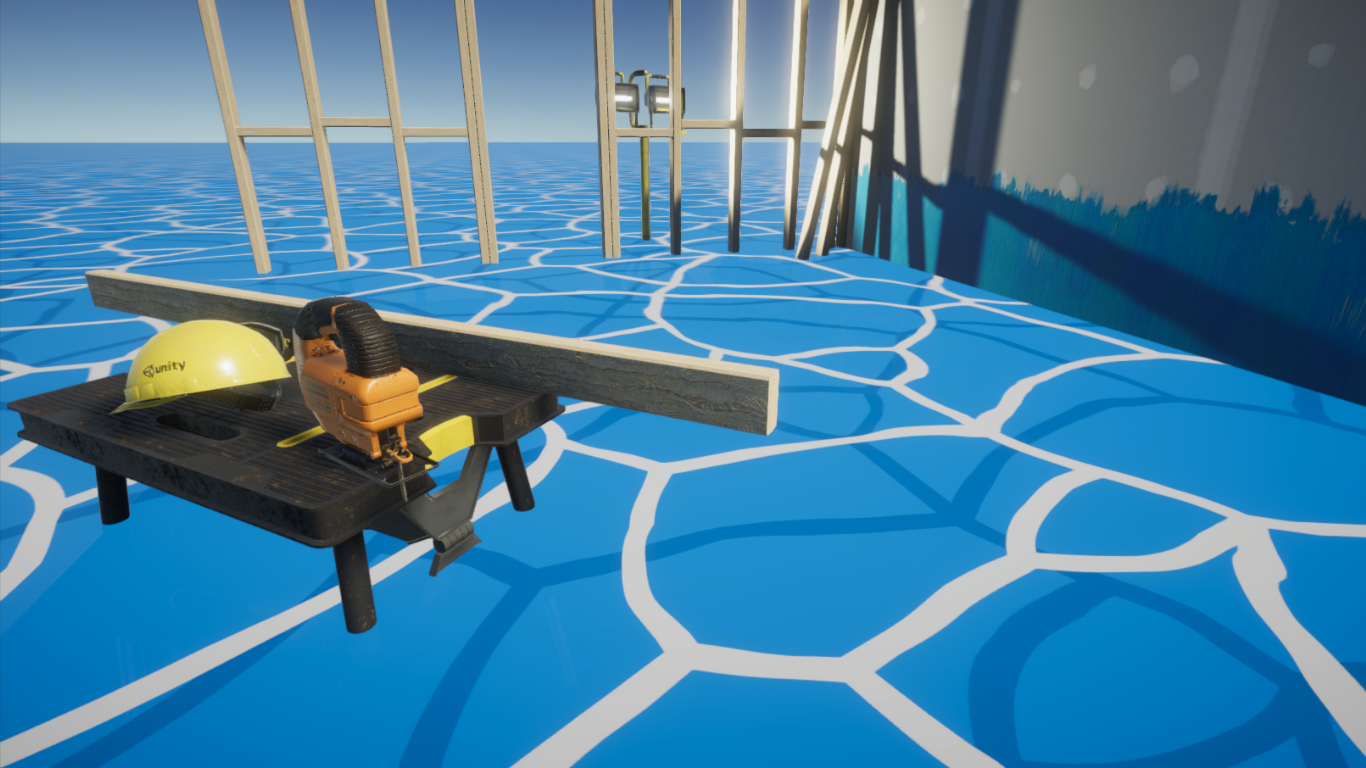
The Great Sea is made up of a great expanse of blue, broken up by rings of foam, as you can see in the below screenshot from the game. In some sections, there’s a similar but darker ring pattern that shows up underneath the foam - we’ll include them both in our effect. Because it’s an ocean, there’s sections where the waves are a bit choppier, so we’ll need to wiggle the foam textures around a bit and physically move the water’s surface geometry up and down in a wave pattern. Finally, when an object intersects the surface of the water, we’ll draw a bit more foam around the intersection point.
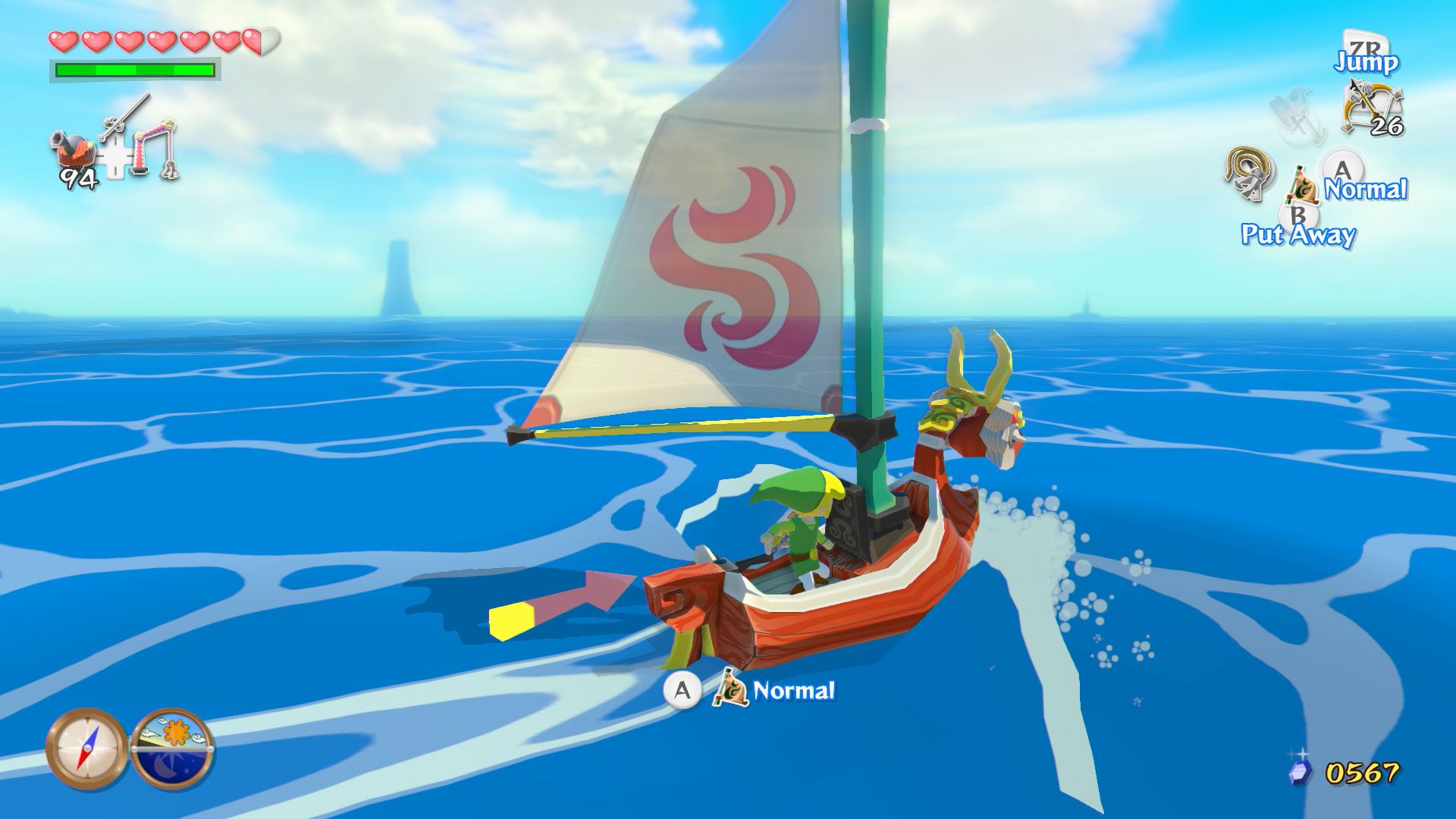 The Legend of Zelda series is keeping me in business.
Flow Map
We’ll be using Shader Graph for this project. The graph can be found in the Assets folder under Shaders/StylisedWater.shadergraph - if you’re working from scratch, then create a new Unlit Graph. We’ll go through each section of the graph in order, starting with the flow map. The foamy surface of the water needs to be animated slightly to look as if the water has motion - if we kept a static texture, then even once we’ve added waves via vertex displacement (that’s much later on in this article!) then the foam will look a bit rigid. To animate the foam, we’ll distort the UV coordinates used to sample the foam texture according to a ‘flow map’. This flow map contains normal data arranged in such a way that each pixel normal describes which direction a fluid will flow toward, and we can use those normal vectors to offset the UVs we use to sample the foam texture. In fact, this process will look familiar if you read by underwater post process effect article - we’ll even use the same flow map.
For the flow map, we’ll need to animate it over time. We also want to be able to control the flow speed and flow texture/map in the material Inspector as well as the flow strength, and while we’re there we’ll add a size property - we’ll need it when we sample the foam texture, but while testing things out I discovered that as size increases, it looks better if the flow amount decreases. Both can be tweaked in the material Inspector anyway.
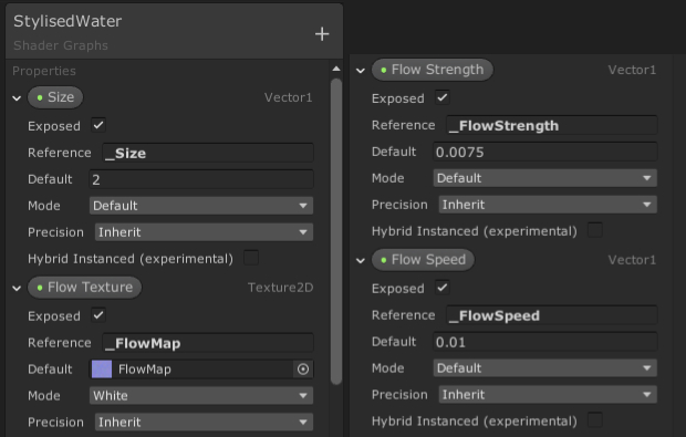 These are the properties we’ll use for the flow map.
Let’s start easy and just poll the flow map texture using a Normal From Texture node, then Multiply its output by the Flow Strength property.
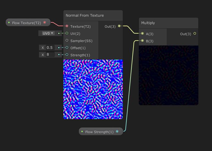
Normal From Texture removes the need for a separate Sample Texture 2D node.
Then, we’ll modulate the UVs on the Normal From Texture node over time. Start by creating a Divide node to divide the Flow Speed property by the Size property. As I mentioned, this prevents large patches of water flowing strangely. Then, Multiply the output by a Time node using its regular Time output. This will allow the normals to scroll over time. You’ll need to Add this value to a UV node, keeping the drop-down value at UV0. The final output of the Add node gets funnelled into the UV input of Normal From Texture.
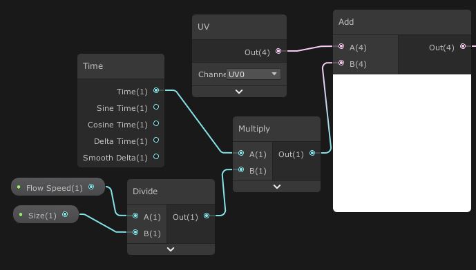 We can modulate the UVs over time and with varying speed and strength.
Everything we’ve created so far can be bundled into a group called “Distort UVs based on Flow Map”.
Voronoi Texture
Now we’ll sample the foam texture. The water in The Wind Waker has loads of blotchy patches of foam - at first I thought of using Unity’s built-in Voronoi node to generate a randomised grid of blotches, but I settled on the far easier method of using a Voronoi texture. I found a good one online and modified it so that the grid lines of each cell are white and the background is black, then I made a variant with slightly curved lines and a couple of smaller cells. It’s up to you which one you use - both are in the Textures folder.
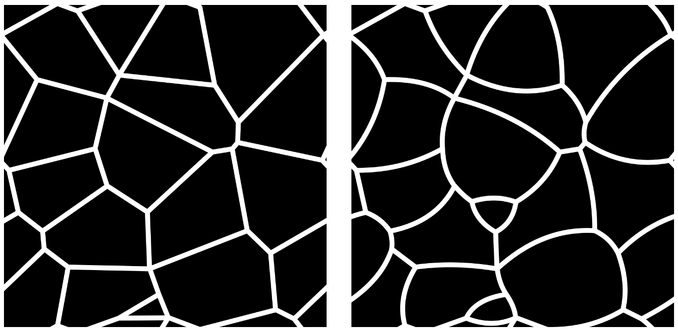 There are two variants of the Voronoi foam texture depending on your preference.
We’ll add a new property called Foam Texture of type Texture2D, assigning one of the voronoi textures as a default value. Then, we’re going to Add the result of the existing flow map distortion group of nodes to a new UV node. We’ll Multiply that by the Size property - since larger sections of water will need to tile the foam texture more - and finally feed that into the UV input of a Sample Texture 2D node, which takes Foam Texture as its Texture input.
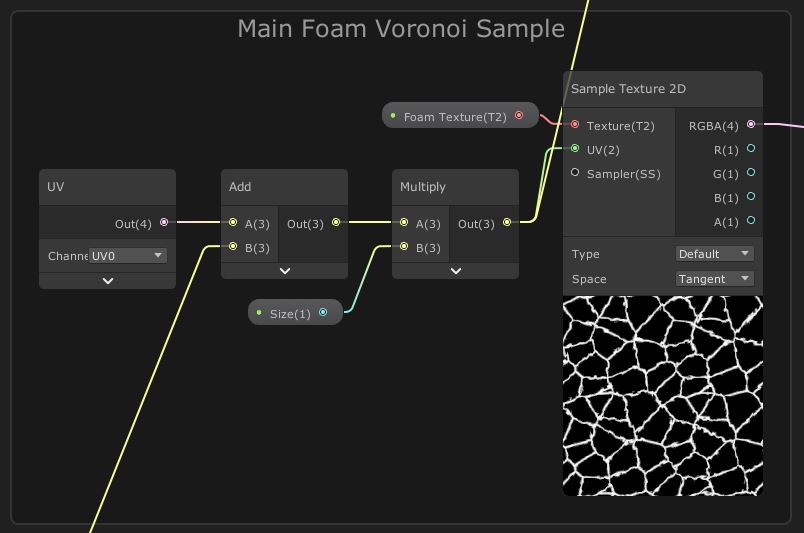 We’ll eventually have a lovely foam pattern on the water’s surface.
You’ll notice we haven’t provided any colouration yet. The final product will need three different colours: Water Color, Light Foam Color and Dark Foam Color - create a new Color property for each of them. I’ve made the light foam colour totally white, then the water is a nice shade of blue and the dark foam is a darker shade of the same blue. Now let’s add the darker foam pattern. On the previous screenshot, you’ll see a connection shooting off the top of the screen - it’s connected to an Add node with a constant value of (0.1, 0.1, 0.0) in the second input. The result of that is used for the UV input of a second Sample Texture 2D node, which also samples Foam Texture. We’re using almost the same UVs we used for the first texture sample, but they’ve been shifted very slightly so we offset the dark foam pattern. We’ll provide the first bit of colouration here by using the output of this texture sample in a Lerp node’s T parameter, with the Water Color and Dark Foam Color in the A and B inputs respectively.
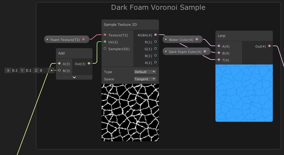 We’re starting to see what the final texture will look like.
Now we can combine everything we’ve done so far. Plug the result of the dark foam group into a new Lerp node, with the Light Foam Color as its second input. The T input should be the output of the main foam group. Then, plug the result of the Lerp node straight into the Color channel of the Unlit Master node.
 The colours are all correct and the surface texture animates slowly.
Intersection Foam
We would stop here, but we also want to add foam where objects intersect the water, and it’d wrap things up nicely if the water had waves that reach up high. To add foam, we’re going to compare the depth of each pixel being drawn on the water surface with the depth that’s already in the depth buffer - if the difference is small, then an object is intersecting the water - we can draw the foam colour at these points. We’ll need to add a new Vector1 so we can control how far objects can be away from the surface before they stop registering as an intersection - we’ll call the new property Foam Distance and give it a default of 1.5.
Let’s start by getting the depth already in the depth buffer. For that, we’ll use the modified UVs we created in the first step and Add those to a Screen Position node - this will let us make the intersection foam distort slightly on the water’s surface. We’ll use the output of that in a Scene Depth node, with its mode set to Eye (which converts the depth to eye space) - this output provides the depth of whatever object is already in the depth buffer at this position.
From this, we’re going to Subtract the screen position of the water pixel we’re currently drawing - for that, we’ll use a Screen Position node (set to Raw), with a Split node being used to retrieve the w-component of the screen position. The explanation here is a bit tricky, but basically, using the Raw mode means that the position values haven’t yet been projected onto the 2D screen - that means the w-component still contains, essentially, the depth. We’ll Divide its output by Foam Distance to set up the cut-off point where objects stop registering as an intersection, Saturate the output to clamp its values between 0 and 1, then use a Step node with an Edge input of 0.5 to perform the cut-off.
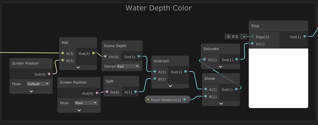 These nodes will let us calculate where intersections occur.
To incorporate the output of this node into the rest of the graph, we’ll insert a new Lerp node between the Unlit Master node’s Color input and the Lerp node that’s already connected to it. Insert the output of the Step node into this new Lerp node’s T parameter and use Light Foam Color for the A parameter and the output of the existing Lerp for the B parameter. It’ll look something like this.
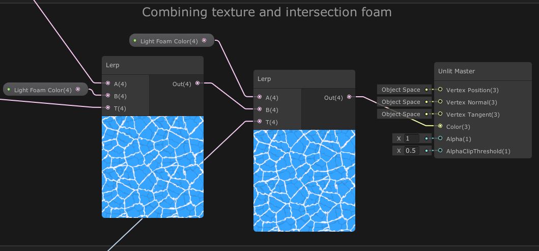 Combining all foam and texture calculations.
And here’s what the scene looks like.
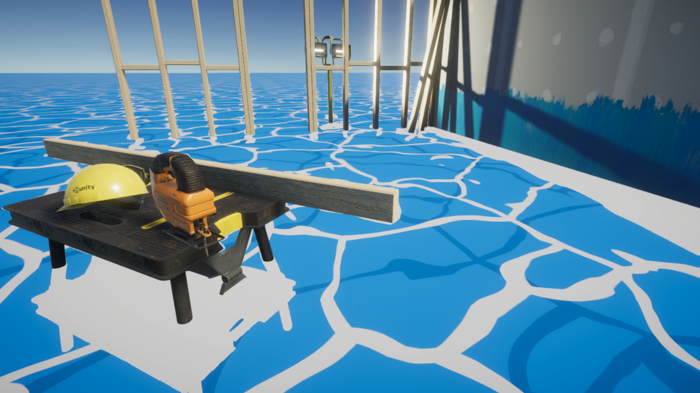 An almost-complete water effect, complete with intersection foam.
Vertex Displacement
The final step is to displace the vertices of the mesh over time to simulate waves. We’ll add another Vector1 property called Choppiness, giving it a default value of 0.01. You might have noticed so far that there’s been no mention of vertex shaders anywhere in Shader Graph - however, they do exist! The Unlit Master node contains three inputs - Vertex Position, Vertex Normal and Vertex Tangent - which let us modify the vertices. We need to use a sine wave with time as an input. We’ll also need to factor in the x- and z-components of the vertex’s world position too, or else the entire mesh will bob up and down at the same time!
Start off with a Position node, with the Space set to World. Use a Split node to separate the components of its output, then Add together the x- and z-components. Use another Add node to add those components to a Time node’s basic Time output, and then Multiply everything so far by Choppiness. We’ll pass this into the y-component of a new Vector3 node, and create a new Position node, this time in Object space - Add both together and hook it all up to the Vertex Position pin of the Unlit Master node. For one final adjustment, I also created an Opacity property and connected it to the Alpha channel of Unlit Master.
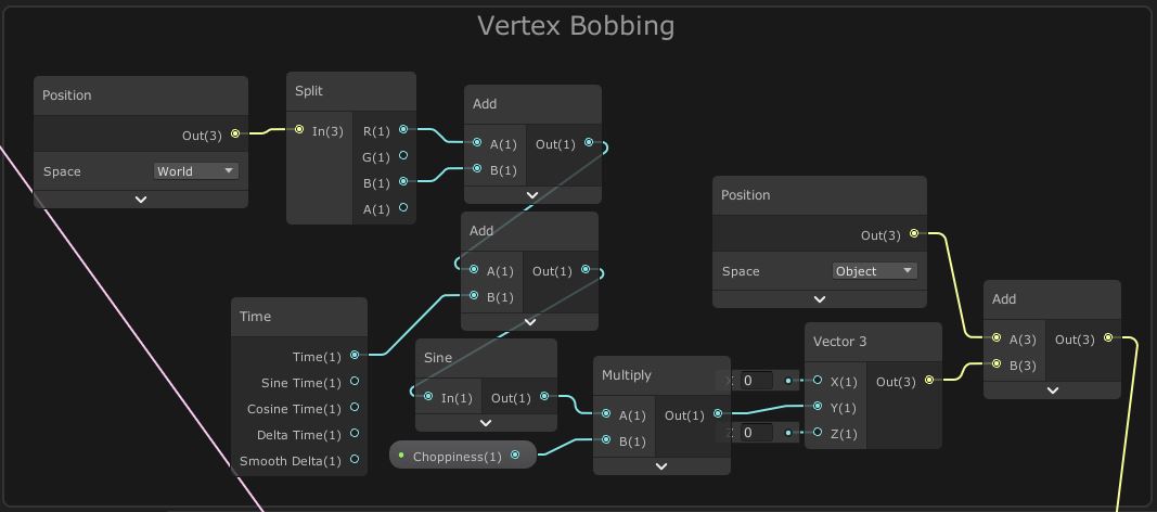 We can manipulate vertex data in a Shader Graph.
And now, with everything in place, we can enjoy the resulting water simulation!
I’m pleasantly surprised by the performance of this effect - I spawned in 1024 separate water meshes, and on my GTX 1070 I managed to still reach almost 400fps.
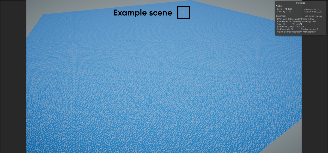 This effect is surprisingly performant!
Conclusion
There are plenty of ways to create a stylised water effect in Unity URP. A good way of emulating the water in The Legend of Zelda: The Wind Waker is to use a voronoi pattern for the surface foam, muddle around the UVs a bit with a flow offset, add even more foam at intersections and offset the water mesh vertices to act as waves.
More URP content is coming soon - stay tuned!
By the way, if you’re looking for a water asset for your games, then here’s one I really like: